
FluidSIM
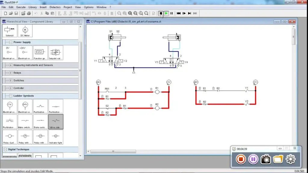
FluidSIM is a handy solution that enables you to design, learn, and simulate from a single place. It is a prominent and well-regarded simulation and circuit diagram design program developed to be used in multiple areas such as electrical engineering, pneumatics, and hydraulics. It makes it easy for the audience to design circuits and give them shape via learning and simulation, requiring them to spend little effort.
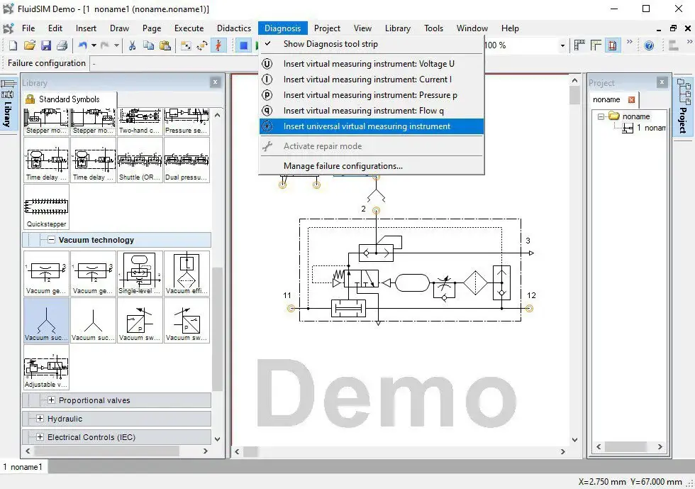
You can structure the lessons without the hassle and create profiles that show only the desired components, functions, and options. This functionality is termed the “expert mode”. Students and teachers will find the software easy to use. Furthermore, instructors have the ability to share specific libraries with students. This gives students the opportunity to work without problems and focus on the exercises. It has convenient documentation with evaluations that are freely definable, allows exports in popular formats, and enables individual drawing frames in all sizes.
It provides several libraries for the latest technologies like Circuits with contact, Vaccum technology, Mobile hydraulics, Actuators in pneumatics, and more. The solution comes included with education content with video sequences, slides, sectional drawings, pictures, animations, information of the modules with a single click, option to switch language with multiple translations for French, German, Spanish, and English. There is also a dedicated training program meant to guide newbies. Other characteristics include Flexibility to use and installation, Real-time testing, a broad range for full comfort, high-definition Simulation, and Professional CAD.

FluidSIM Alternatives
#1 Virtual Breadboard

Virtual Breadboard is a freeware design and learning solution that comes with all the essential features to enable the creation of intelligent connected electronic applications, allowing you to achieve your tasks at no cost. It is available on Hub, HoloLens, Mobile devices, and PC. The tool is the right choice for those looking to enhance their knowledge. You can select applications and drop them via the ever-increasing collection of virtualization components, resulting in time-saving.
The features include interactive virtualization to enable circuit testing and learning based on exploring and the ability to build solderless Virtual Breadboard circuit applications with great ease and in no time at all. Before committing to a build, you can test circuit layouts to see them in action. It provides a microcontroller and circuit emulator for testing circuits and the code. Another key feature is the freedom offered to the end-user for experimenting with microcontroller-based electronic circuits with full safety.
#2 Circuit Simulator

Circuit Simulator is a top-notch and online animated electronic circuit simulator that provides a visual look of voltage and current using ideal components. It is developed using JavaScript, and upon launching it, you will get a view of an animated schematic of a plain LRC circuit. The tool uses five colors to inform about different situations.
The positive voltage is indicated through a green color while the ground is displayed via gray color. The red and moving yellow colors are utilized to highlight negative voltage and current, respectively. The interface consists of various buttons such as File, Edit, Draw, Circuits, Options, and Scopes. The Circuits button in the UI lest you access A/C Circuits, Passive Filters, Diodes, Op-Amps, Active Filters, Blank Circuit, Logic Families, Combinational Logic, MOSFETs, Transmission lines, Sequential logic, 555 Timer Chip, and more.
#3 OpenModelica

OpenModelica is a freeware and open-source Modelica-based simulation and modeling system that is designed to be used for academic and industrial purposes. It is actively being maintained by a non-profit organization called the “Open Source Modelica Consortium,” which is the sole entity responsible for its long-term development. The aim is to provide a full-fledged Open Source Modelica modeling simulation and compilation environment that uses publicly available software for development.
These open-source packages are mainly intended for industrial, research, and instructional usage and enable the audience to enhance their knowledge without paying for it. The tools include Modelica Development Tooling, OpenModelica Compiler, OpenModelica Matlab interface, OpenModelica Shell, OpenModelica Python Interface, and OpenModelica Notebook. The OpenModelica Compiler or OMC for short converts Modelica into C code, providing a symbol table consisting of definitions of variables, classes, and functions. The OpenModelica Python interface is another great feature that allows you to use the simulation and modeling abilities of the tool via Python.
#4 Logicly

Logicly is a robust logic circuit simulator developed for macOS and Microsoft Windows to enable you to deliver concepts related to digital circuits and logic gates with full effectiveness. It provides an easy-to-use interface that comes in handy for designing circuits with great ease. The designing part can be taken care of quickly, which is thanks to the drag-n-drop, zoom, copy/paste, and other features quickly. It provides debugging functionality which can be initiated by pausing the simulation and seeing how the signal propagates with each step.
There is no need to fret about multiple platforms. Just install on both macOS and Windows and start teaching. Instructors/teachers can create stunning, engaging assignments for students and give their students the freedom to get their hands dirty with the simulation by providing the ability to undo. This will remove the pressure from their shoulders and generate the confidence necessary for building physical circuits with full confidence.
Create custom integrated circuits to encapsulate and prevent copies. These can also be dragged and dropped like gates. You can customize the solution according to the demands of the curriculum by creating libraries of custom circuits, which can then be imported by students in their work. It supports all the standard gates such as XNOR, AND, NOR, OR, NAND, NOT, and XOR. It also comes with serval primitives like pull up/down resistors and tri-state buffers. Other features include Truth tables, International symbol standards, Edit multiple files, Simulation controls, Zoom and Pan, Print, Undo and Redo, Strict or loose mode, Bundle custom objects, Logic signal types, Save files, International symbol standards, Import/export circuit libraries, and more.
#5 PartSim

PartSim is a fully-featured and robust circuit simulator that you can use from your web browser. It is easy to use and can be used without paying any fees. The highlights include SPICE Simulator, Waveform Viewer, and DC/AC/Transient Sims. Other worth mentioning characteristics include a complete SPICE simulation engine, graphical waveform viewer, and a fully web-based schematic capture tool. You can explore various examples given on the official website and experiment with them to become more comfortable with the solution. Another thing worth mentioning is the Arrow Integration which grants you the ability to assign Arrow Part Numbers to the models with great ease.
#6 Micro-Cap

Micro-Cap is a free-of-cost SPICE simulator developed by Spectrum software. It is fully compatible with analog/digital circuits and allows electronic engineers to use the built-in interactive sketch and simulate the environment through an integrated schematic editor. It used to be paid but was recently made freely available to the public by the owners. The modules include Interactive Editing and Simulation, which provides robust simulation choices. Simulation options can be accessed with a single click and become available upon the creation of a schematic.
Transient analysis is offered for the simulation of the time domain along with AC and DC analysis for small signal frequency simulation and DC simulation, respectively. Other analysis tools include Monte Carlo analysis, sensitivity analysis, harmonic distortion analysis, and intermodulation distortion analysis. Another great component is the Native Digital Simulator that allows you to run mixed-mode or digital simulations through models that are owned by you or ones selected from the extensive digital library.
The key highlights of this specific component include Hazard reporting, fast, event-driven, and 5-state simulator, and availability of more than 2000 standard digital parts belonging to various digital families, including ECL100K, 7400, ECL10K, HCT, AC, LV, ALS, F, H, ACT, S, and more. Other modules include Worst-Case Analysis, Smoke Analysis, Optimizer, Filter Designer, 33,000 Part Library, and Analog and Digital Behavioral Modeling.
#7 Pspice

Pspice is an advanced circuit simulation and analysis software for analog and mixed circuits. It allows engineers to make virtual prototypes of designs and maximize circuit performance by altering the situations. It combines Sensitivity, Monte Carlo, Smoke analysis, parametric analysis, and an Optimizer to provide an expanded environment to take design analysis beyond simulation. The Pspice Advanced Analysis Option maximizes design performance, yield, cost-effectiveness, and reliability. Automatic performance optimization algorithms improve design quality and engineer productivity.
You can find optimum combinations of component values, automatically simulate, evaluate results and adjust component values to reach performance requirements. It allows you to retarget existing designs with new goals without modifying the layout. Pspice’s tight integration with schematic tools allows for improved accuracy. You can directly set up and run simulations and cross-probe simulation result from OrCAD Capture. View simulation bias results directly on the schematic, including node voltages, pin, and sub-circuit currents and device power calculations. All in all, Pspice is a great productivity tool for engineers and circuit designers.
#8 NI Circuit Design Suite Power Pro

NI Circuit Design Suite Power Pro combines Multisim and Ultiboard software to offer a complete set of tools for circuit design, simulation, validation, and layout. It helps you design circuits using intuitive and cost-effective tools. You can perform interactive SPICE simulation and seamlessly transition to PCB layout and routing software. The tool is built for education, research, and design; the suite provides advanced simulation capabilities to give you clear insights into how circuits perform under any situation.
Multisim software integrates industry-standard SPICE simulation with an interactive schematic environment to instantly visualize and analyze electronic circuit behavior. Its intuitive interface helps educators reinforce circuit theory and improve retention of theory throughout the engineering curriculum. By adding powerful circuit simulation and analyses to the design flow, Multisim helps researchers and designers reduce printed circuit board prototype iterations and save development costs. Multisim Live delivers SPICE simulation to you anywhere, anytime. With a database of over 30,000 community circuits, you can immediately turn inspiration into simulation.
#9 Oregano

Oregano is an open-source graphical software application for schematic capture and simulation of electrical circuits. The actual simulation is achieved by the SPICE, Ngspice, or Gnucap engines. The software makes use of GNOME technology and is meant to run on free Unix-like operating systems such as Linux. The easy-wire mode lets you connect elements with fewer clicks and less frustration. Cross-window copy/paste allows you to easily explore and re-mix parts of public circuits from the Oregano community.
With the Unit-aware expression evaluation, the Oregano plot arbitrary signals of interest, such as differential signals or power dissipation, design and analyze faster, and above all, you can do arbitrary Laplace transfer function blocks with it. All in all, Oregano is a great circuit designing and simulation tool for beginners as well as pro users.
#10 Solve Elec

Solve Elec is a lightweight program that allows you to draw and analyze direct and alternating current electrical circuits. Some highlighting features include verification of circuit-related problems, graphs drawing, browse and integration of documents, edit, save and print reports that are made of multiple elements displayed in the main window. You can get literal formulas and values for current intensities and voltages defined in the circuit. Other features are oscilloscopes, filter analysis, formulas transfer functions, values of transfer functions, and frequency response graphs.
The interface is neat and tidy, with a sidebar that includes all the tools, a bottom space where you will be able to see the properties of each project, and an area on the right to solve the formulas or view behavior graphs. There are also curve functions that help draw intensity and tension curve values on a graph. The plotted graph uses different colors to highlight different state functioning, like linear, active, and saturation mode for a transistor’s characteristics, each of which is described by the graph legend. You can turn off the legend to make modifications to the graph.
#11 PCBWeb

PCBWeb is a PCB analyzer and simulator that aims to assist engineers and programmers in designing and programming circuit boards. PCBWeb Designer contains a fully integrated component catalog allowing you to easily search, filter, and place parts that have both a symbol and footprint. Ports in PCBWeb Designer allow you to make sheet-to-sheet connections in your design, which is especially needed for parts with large banks of I/O pins. PCBWeb Designer provides basic text and shape objects to help annotate your design. Simply choose the Draw icon in the main toolbar to place a polyline, circle, rectangle, or arc object.
Once an object is placed in your design, right-click on the object and choose properties to edit its attributes, such as color or line type. PCBWeb Designer supports multi-sheet schematics, which are especially useful for large designs. It also supports the filters that allow you to mask specific objects during the layout of your design. The filters improve efficiency during design by limiting the total number of objects in your section mask.
#12 BlackBoard Circuit Designer

BlackBoard Circuit Designer is an open-source design tool for perfboards and electrical circuits written entirely in Java. It allows you to easily create simple and easy-to-read schematics. With the NGSpice integration, the Blackboard Circuit Designer simulates the current schematic. The editing is based on a huge library of electronic parts with more than 400 pieces and a library with 500 symbols and integrated parts. Blackboard is intended for the hobby enthusiast and should help to build prototypes on so-called breadboards easily. All in all, BlackBoard Circuit Designer is aimed at beginners with some basic tools and features.
#13 PCB Wizard

PCB Wizard is a powerful simulation tool that you can use to design and simulate PCBs and their functions. You can design single or double-sided PCBs and provides comprehensive tools for covering all traditional steps in PCB production, including schematic capture, schematic capture, component placement, bill of material reporting, automatic routing, and file generation placement. Additionally, PCB wizard offers some features that do away with the steep learning curve normally associated with PCB packages. The tool doesn’t need much heavy hardware resource as it is a lightweight tool that can even run on old systems.
Other features include Schematic design of diagrams, expandable component library, automatic connection between design elements, zoom in up to 10x, copy and paste to other software, undo and redo functions, integrated drawing functions, and text functions. All in all, PCB Wizard is a highly innovative package for designing printed circuit boards, offering unrivaled productivity through powerful design tools and an ultra-friendly user interface.
#14 McCAD 3SPICE

McCAD 3SPICE is a simulation software based on the latest version of Berkeley’s SPICE 3 engine and permits interactive mixed-mode circuit simulation. It is developed specifically to take advantage of the processing speeds available, thus permitting extremely fast simulations. The tool can run in a conventional standalone configuration or fully integrated with McCAD Schematic Plus, and providing the designer with schematic capture, simulation, and graphic waveform generation is a fully integrated environment. The 3SPICE simulator provides accurate and flexible modeling of semiconductor devices, passive elements, and ideal switch components. 3SPICE models include MOSFETs, GaAs MESFETs, resistors, capacitors, inductor models, lossy transmission lines, Coupled transmission lines, Voltage, and current-controlled switches.
The 3SPICE simulator module allows you to analyze your simulation results and view them in a variety of ways. You can apply complex math operations on the resultant data, such as finding the phase, magnitude, calculate the derivative, sine, cosine, tan log, and natural log. Graphical annotation allows you to mark up and make illustrations directly on your plot results, making it useful for generating reports.
#15 MacSpice

MacSpice is software for simulating and analyzing electronic circuits that can vary in complexity from a single transistor to a complex integrated circuit with thousands of devices connected. The software is widely used by students, teachers, and engineers. The software is available for both Windows and macOS. MacSpice requires text files as a description of circuits. MacSpice offers several mechanisms for communicating with other applications. This feature greatly expands the range of problems it can tackle; other applications can compensate for MacSpice’s weaknesses or exploit its strengths.
The MacSpice console has command and files finishing point and command-line editing keystrokes. MacSpice has a node-set command that saves the state of its current analysis as a file of node-set commands suitable for inclusion in a netlist. This is useful in cases where the operating point is difficult to find. Al in all, MacSpice is a great cross-platform simulation and analysis tool for designing the electrical circuit and saving the cost of the actual prototype.
#16 PCB Artist

PCB Artist is an advanced PCB layout software that comes in handy if you are an engineer or engineering student. It saves the cost of manufacturing actual PCB design by making a virtual working electronic circuit. The two main features of PCB artists include the ability to create a schematic and layout. A schematic is a detailed visual representation of all the components the user would include in their layout. Schematics include the wire connections between each component, net names, and classification of the signal for the layout as a power, signal, or ground signal.
Another highlighting feature of PCB artist is Advanced Circuit that continuously updates the library in each software update to maintain the most recent components on the market. PCB Artist also includes the footprints of many general components that a user can use to refine to specific ports. The process for PCB design is to first create a list of parts you will use in the circuit, then search for these parts in the libraries available. If the parts are not in any of the available libraries, you must create the components. This includes making a schematic symbol, a PCB symbol, and then creating a component that will connect the two together in order for the program to relate the schematic to the PCB design. All in all, PCB Artist is a lightweight yet handy tool for simulating PCB designs.
#17 DCACLab

DCACLab is an online virtual PCB simulation and analysis lab that allows you to apply scientific methods, use tools, equipment to draw circuits, and draw conclusions. The virtual lab experience involves hands-on activities plus virtual experiences in a lab-like setting. This lab, therefore, provides learners with virtual experiences that engage them in a realistic manner as they maintain the integrity of similar hands-on lab activities. Every component explains its own function and the basic electricity relationships.
It allows you to create circuits out of schematic drawings, make use of a voltmeter and ammeter to take circuit readings, provide a logical explanation of the measurements as well as the circuit relationships, explain basic electricity relationships both in parallel and series circuits, and develop a theory for explaining the circuit measurements. The tool helps you find the resistance of different objects using the virtual lab. You can also discuss the charging and discharging processes of a capacitor in a circuit. All in all, the DCALab is a great PCB design tool for beginners and students who want to take the first step in the electronics industry.
#18 PSIM Software

PSIM Software allows engineers to perform electronic circuit simulation and analysis used in motor drive or powering electronics. The software comes with multiple modules like Motor Drive, Spice, Digital Control, etc. The modules are well-implemented and quite easy to integrate with platforms as JMAG, Modelsim, Simulink, or TI kits. With the Digital Control feature, you can analyze systems in the z-domain and convert the signal from analog to digital control. This flexible module allows users to save execution time.
The Renewable Energy module allows you to simulate, manipulate and analyze a renewable power system with the aid of innovative models for solar, wind, and battery storage systems. PSIM Software has a much faster simulation speed than SPICE-based simulators based on its usage of the ideal switch. With the additional Digital and SimCoupler Modules, almost any kind of logic algorithm can be simulated. All in all, the PSIM Software is advanced software that you can consider among its alternatives.
#19 Fortex Circuit Wizard
Fortex Circuit Wizard is an advanced circuit designing tool that allows you to design, simulate, and analyze the circuit with its comprehensive set of tools. By integrating the entire design process, the Fortex Circuit Wizard provides you with all the tools necessary to produce an electronics project from start to finish. Unlike typical design software, the Fortex Circuit Wizard can perform additional tasks, including schematic capture and simulation, breadboarding, PCB layout and simulation, bill of materials reporting, and file generation for manufacturing.
Scheming is easy with Fortex Circuit Wizard. Just grasp the apparatuses you need from the library, link them together using Circuit Wizard’s quick wiring tool and then press the Play button to begin the model. Some other features include a large component database, manual PCB design, single and double-sided auto-routing, copper pour, Gerber and N.C. drill export, etc. For recording circuit measurements, Fortex Circuit Wizard provides you with seven virtual instruments. It includes an oscilloscope, digital and analog multimeters, a logic analyzer, a wattmeter, a signal generator, and a word generator that drives a circuit by generating streams of 16-bit words.
#20 NI Multisim

NI Multisim is a PCB design and simulation software that is a part of the NI Circuit Design Suite. It provides an intuitive schematic environment to quickly visualize and analyze electronic behavior. By adding powerful circuit simulation and analyses to the design flow, the NI Multisim tool helps researchers and designers reduce printed circuit board (PCB) prototype iterations and save development costs. The software comes in two versions. Ione is for education that includes teaching style application with courses and labs included. The other is Multisim for Designers that provides engineers the SPICE simulation, analysis, and PCB design tools to quickly iterate through designs and improve prototype performance.
NI Multisim software combines SPICE simulation and circuit design into an environment optimized to simplify common design tasks, which helps you improve performance, minimize errors, and shorten the time to prototype. With a library of 55,000 manufacturer-verified components and seamless integration with the Ultiboard, you can confidently iterate through design decisions and annotate changes between layout and circuit schematic.
#21 gEDA Project

gEDA Project has been providing and is being used on a complete GPL’d suite and toolkit of Electronic Design Automation tools. The fields where these tools are being used include prototyping and production, electrical circuit design, simulation, and schematic capture. The platform offers an advanced suite of free software applications that help in different areas of electronics design, including analog and digital simulation, electronics design, bill of materials generation, printed circuit board layout, and more.
The idea of the project was to end the scarcity of free EDA tools for the POSIX system and to drive advancements for free hardware or open-source hardware. The development of the suite is carried out on GNU/Linux platform, and the aim is to release tools for other platforms in the near future.
#22 DIYLC

DIYLC sort for “DIY Layout Creator” is a prominent drawing tool that is the result of a collaborative effort between various developers passionate about DIY electronics. Several ideas of the solution have originated from previous versions of the applications. The primary purpose is to provide the essential tools to the end-user so that they can draw guitar wiring diagrams, schematics, and chassis/board layouts in no time at all. The best feature is that you can draw pretty much anything, which is all thanks to the flexible open-source framework the build uses. The current version of the tool is fully compatible with macOS, Microsoft Windows, Linux, and all those that are capable of running Java JRE.
#23 SimulIDE

SimulIDE is an easy-to-use, noncomplex real-time electronic circuit simulator developed to allow students or hobbyists to gain an understanding of and experiment with microcontrollers, and electronic circuits that support Arduino, PIC, and AVR. The highlights include a limited set of features and less accurate electronic models. It can’t be thought of as an accurate simulator for circuit analysis but does, however, provides fast performance and is easy to use.
The characteristics that allow it to stand out include ease of use and simplicity. There are various tasks that you can accomplish with the tool, such as creating, simulating, and interacting with the circuit by simply selecting a component from the list and placing them onto the circuit. You can test the functionality of the circuit by connecting the components and clicking on the power button.
Another great feature is that it also comes with Debugger and Code Editor for AVR asm, GcBasic, and PC asm. The development is still ongoing because of which you will be able to execute the basic functionalities. The complete set of features include a Serial monitor, Analog and Digital components, Basic Shapes, Oscilloscope, Microcontrollers, Signal plotter, Debugger, Serial port Connection, Code Editor, Subcircuits, and Circuit Animation.
#24 VeroRoute

VeroRoute is a cross-platform solution that enables the creation of 1 or 2-layer PCB, Veroboard, and Perfboard layouts. It is capable of stopping short circuits from occurring and analyzes for open circuits. The features include a built-in tutorial, cross-platform, component editor, save the output in PDF or PNG format, and connectivity visualization and checking. Other characteristics include the ability to create a Bill of Materials (BOM) and export it, Interactive auto-routing, and can change between Vero, Fat, Curved, and Thin track styles very easily. VeroRoute is Cross-platform and is compatible with different OSes such as Microsoft Windows 7, Debian-based Linux system with support for QT version 5.9,5+, and 64-bit Linux Mint 19.3.
#25 iCircuit

iCircuit is an ideal circuit designer and simulator for engineers, students, and hobbyists. It is easy to use and cross-platform, with versions available for Android, iOS, Windows, and macOS devices. It is a powerful simulation engine and is capable of running digital and analog circuits, and offers an analysis module. Engineers, Students, and hobbyists can use it for relevant tasks. The solution works similarly to a CAD program.
You start by adding elements, link them together, and defining their properties. The difference between and iCircuit is that it continues simulating and offers a feel similar to an actual circuit. There is no need to spend time taking measurement or reports configuration, and you can experiment with the circuit as usual. It offers more than 30 elements for building circuits and comes with all the essentials ranging from digital gates to MOSFETs, to simple resistors, to switches.
It has a multimeter which makes it easy to read currents and voltages by probing around the circuit. By adding values to the built-in oscilloscope, the end-user can monitor value changes with the passage of time. The list of supported elements includes Buzzers, Speakers, and Microphones, Dependent Sources, Signal generators, Current Sources, and Voltage Sources, XOR/AND/NOR/OR/NAND Logic gates, LEDs, and DC Motors, Antenna with simulated FM and Am signals, and DACs and ADCs.
#26 BOOLR

BOOLR is an open-source and easy-to-use digital logic simulator developed using CSS3, JavaScript, and HTML5. It runs in Electron and is designed by a group of Dutch high school students studying in their final year to serve as a project about digital logic. It simplifies the creation of digital logic circuits and is fully compatible with Linux, Microsoft Windows, and macOS, and requires no payment from the end-user. Rendering and simulation take place on the same thread. It prevents your screen from freezing by running the simulation asynchronously and in ticks. The source code of the project can be viewed by everyone on GitHub.